Nordfab’s laser welded seam Quick-Fit® Clamp Together Ducting System has been used in many different industrial applications, and under various negative static pressures. The typical design range we see in our applications range from -2" wg to - 28" wg; however, we have some systems operating at vacuums of -32" wg to -42" wg under normal operating parameters.
Our pipe comes in 5' lengths with a rolled lip on each end, thus providing reinforcement every 5', which presents a sound structural design that should be as strong or stronger than any pipe in its class according to SMACNA guidelines and regulations.
All fit-together ducting systems allow for some degree of leakage where they are joined. QF® ducting is no exception and is not sold as an airtight system. In comparison to other ducting typically used in fit-together / clamp-together systems, Nordfab’s QF duct pipe has fully welded, leak-tight laser or plasma welded seams. Spiral and other ducting with lockform seams are not fully welded at the pipe seams and can be expected to have higher leakage rates than QF.
Application of sealants to the individual rolled ends can also enhance the tightness of the system. However, the QF system is sold as a quick way of installing and modifying ductwork while at the same time retaining the usability of each component. In short, QF is designed with the capability to be taken apart, re-assembled, stored or moved. Completely eliminating the possibility for leakage jeopardizes the inherent benefits of the duct.
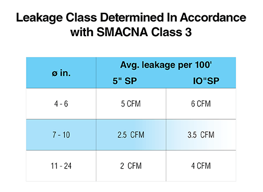
While Nordfab is currently unaware of any method of evaluating dust collection piping alone, the following data is presented using the criteria for all duct, including HVAC. This data is presented only for the purpose of indicating acceptability of the QF in dust/fume removal in a negative pressure situation and should not be confused with the ducting that uses tape or gaskets as sealant in the positive conveyance of air.
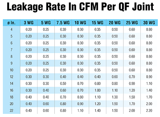
Standard QF ductwork is designed to provide tight sealing and efficient airflow under negative pressures. To that end, we are providing the following information for piping situations where fan sizing is of extreme importance. The following data was obtained using standard components and was performed in accordance with the SMACNA, “ HVAC AIR DUCT LEAKAGE TEST MANUAL”. The information gives the leakage rate per joint of duct at various pressures.
To utilize the chart, count the number of clamps (this equals the number of pieces) per size and multiply by the number given beside the corresponding diameter and under the applicable pressure. These numbers assume that the product is correctly installed, free of dents in the joining ends, and that the gasket is in place. Special gasket material and sealants will increase the sealing capabilities.
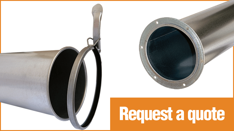
Nordfab Americas manufactures Quick-Fit Ducting in Thomasville NC, USA. Nordfab QF duct is a clamp-together design using a rolled edge design with a single lever clamp. The ducting and clamps are constructed from similar materials.
All clamps contain a standard gasket made of Nitrile which is suitable for most applications, including oil mist, as long as high temperatures are not an issue. Silicone and ePTFE gasket options are available for higher temperature applications.
Nordfab Quick-Fit Ducting is available in 1" increments sized 3" to 24" diameter.
a. Galvanized: ASTM A653 with a G90 rating
i.Recommended max. service temperature is 390° F. At temperatures ranging between 390° F and 480° F, the zinc-iron alloy layers in galvanized steel will continue to provide a high level of protection from corrosion. However, there may be some peeling, changes in mechanical properties, and reduction in the corrosion protection.
b. 304SS: Finish meets ASTM A240
i.Temp rating is 1100° F
c. 316SS: Finish meets ASTM A240
i. Temp rating is 1100° F
a. Diameters 3" - 24" QF pipe, Quick-Fit Sleeves (adjustable nipples), and collars attached to other components will have one or both ends die formed-rolled to provide a uniform edge around the circumference of the rolled end. The pipe and sleeves shall have the longitudinal seam laser welded to allow for a tighter slip joint and reduce system pressure losses. All laser welded seams will undergo a light test to ensure there are no voids or imperfections in the system. Pipe lengths using laser welded seams will not exceed a nominal 60" length. The rolled end is used for clamping components together as well as offering reinforcement Rolled edges provide structural support at 5' intervals or less and can be interpreted as a stiffener where SMACNA specifications are required.
A Quick-Fit Sleeve is used for adjustment during the install process. Pipe is cut to appropriate length and the Quick-Fit Sleeve secures the pipe for install.
b. QF pipe and other QF components larger than 24" shall utilize either an angle flange or flat flange attached loosely and retained in place using a 3/8" vanstone lip. The flanged pipe shall have a solid welded seam and not exceed nominal 60" length. The angle or flat flanges provide structural support at 5' intervals or less and are considered as stiffeners where SMACNA specifications are required.
c. Components which will be air direction sensitive will have an arrow label attached showing the proper flow direction.
a. Clamps shall be constructed with an over-center, spring-lever action for quick connecting of two pieces of ducting. A retaining pin shall be inserted in the handle and an eyelet on the clamp as a safety feature to ensure the handle does not prematurely come undone.
b. When closing the clamp, the internal seal shall be compressed in such a manner as to cover both rolled beads for optimum sealing capacity in a full 360° pattern.
a. Approved caulk is 3M Scotch Seal Metal Sealant 2084 or equivalent for system temperatures of 250°F or lower
b. Optional approved caulk is 3M Polyurethane Adhesive Sealant 540 or equivalent for system temperatures of 250°F or lower
c. Optional approved caulk is Rock River Silicone Sealant or equivalent for system temperatures of 400°F or lower
d. Optional approved caulk is Red Devil HVAC/R High TemperatureSilicone Sealant (red in color) or equivalent for system temperatures of 500°F or lower
e. Sealing o-rings
i. Buna-N, ASTM D2000 MBC610, 60 Durometer Hardness, with a temperature rating of 250°F maximum and is black in color, used with the Quick-Fit Sleeve.
ii. Silicone rubber, ASTM D2000 MGE705, 70 Durometer Hardness, and is red in color, used with the Quick-Fit Sleeve.
f. Sealing gaskets
i. Molded gaskets shall meet the material classification of ASTM D-2000 M2BG510 A24 B34 EO14 EO34 EF11 EF21 and used in systems where the temperature rating is 225°F or less and are black in color. This component shall be made using conductive materials for conductivity.
ii. Sponge o-ring shall meet the material classification of either ASTM D-1056-68 – SBE43 or ASTM D1056-85, 91, 98 – 2B3
g. Clamp seals shall be made of one of the following:
1. Nitrile to meet or exceed ASTM D1056 2B2 standards with a temperature rating not to exceed 158°F constant temperature (or intermittent temperature of 194°F).
2. Silicone to meet or exceed ASTM D1056 2D2 standards with a temperature rating not to exceed 400°
3. ePTFE not degraded by any common chemicals in the 0-14 PH range. Temperature rating shall not exceed 600°F.
Metal-to-metal contact shall be obtained at all joint connections. Die-formed rolled edges are uniform in shape which provides the most consistent contact. The ears of the clamp contact with the rolled edges and provide maximum conductivity. Conductivity shall be adhered to per NFPA 77 paragraph 8.4.1.1; states all parts of the continuous metal piping system should have a resistance level that does not exceed 10 ohms. Testing is the responsibility of the owner.
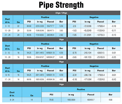
Each size of duct piping has been third party tested for strength against collapsing. The piping was exposed to constant Positive pressure and constant vacuum. This testing was performed with sealed standard lengths of QF Pipe. Air was then slowly introduced as negative or positive pressure and the maximum value was held for 3 minutes. The table below reflects the values held.
For individual product specifications, see our Products pages - search for the product of interest and click on the pdf under the Resources section - or download the product data sheet here.
NOTE: Manufacturing specifications are subject to change as we update our equipment and processes. Please contact Nordfab for additional information.
For immediate assistance, call us at 800-532-0830.